
TOOLING PROJECT · ABS+PC SEAT SHELL
Child Car Seat Injection Mold: Cooling and Core Pulling
A single-cavity tool combining a central hot runner gate, targeted deep-rib cooling and six hydraulic core-pulling cylinders.
DFMOLD HK developed this child car seat injection mold around three connected challenges: filling a deep shell, removing heat from its ribs and releasing the undercuts around the base. The project progressed from CAD and CAE review to tool machining and shipment preparation.
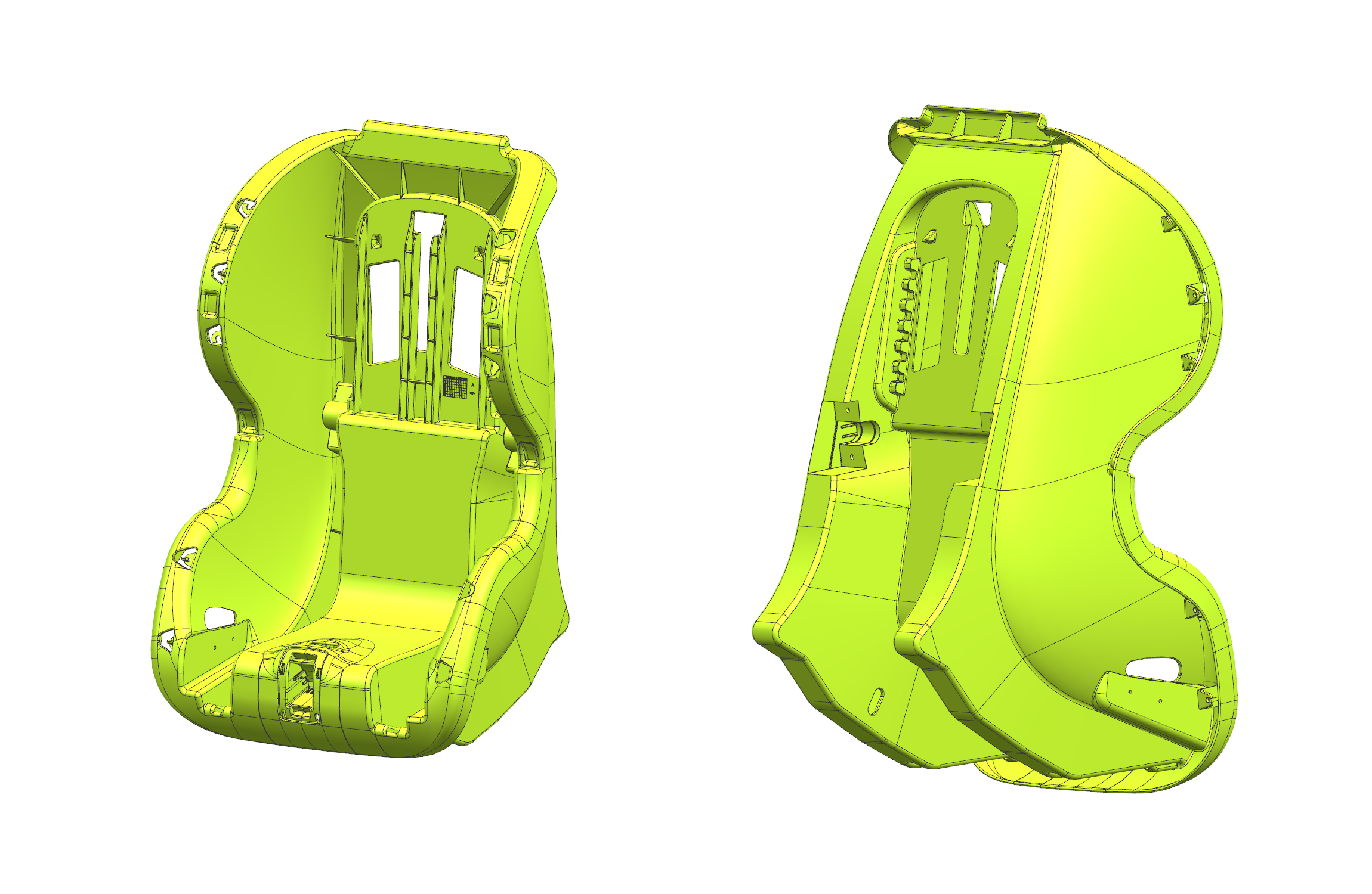
Project at a glance
| Component | Child car seat structural shell |
|---|---|
| Resin | ABS+PC blend |
| Tool layout | Single cavity; two-plate mold |
| Gate system | Single central YUDO hot runner gate |
| Specified tool steel | 718H for cavity and core |
| Side actions | Six hydraulic cylinders with sequenced core pulling |
One gate, checked against the whole shell
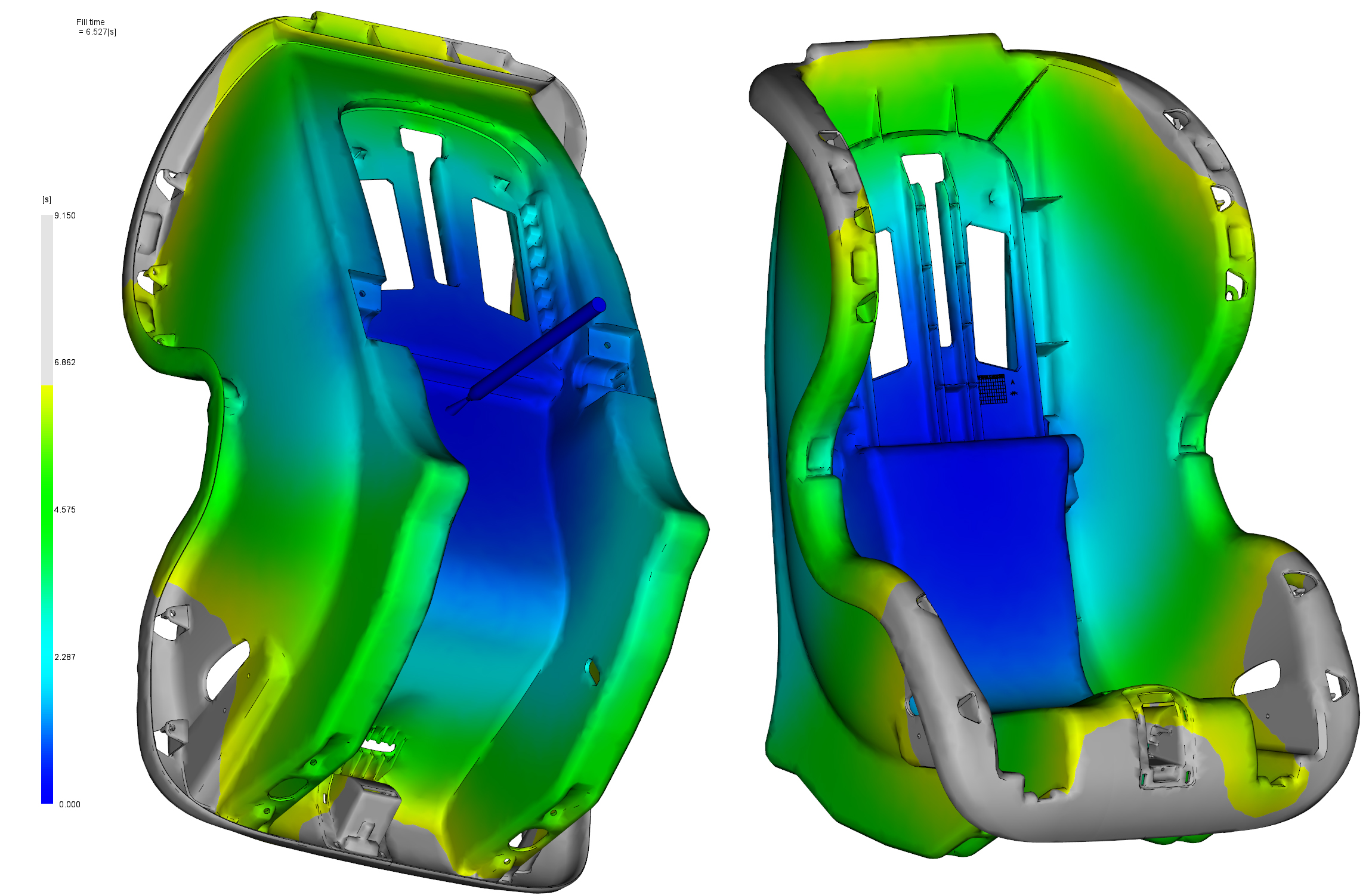
The central gate location was evaluated through CAE filling analysis. The review followed flow into the backrest, side walls and lower corners, where the geometry changes direction. The analysis supported the single-gate approach and did not identify a major air-trap concern in the lower corner region.
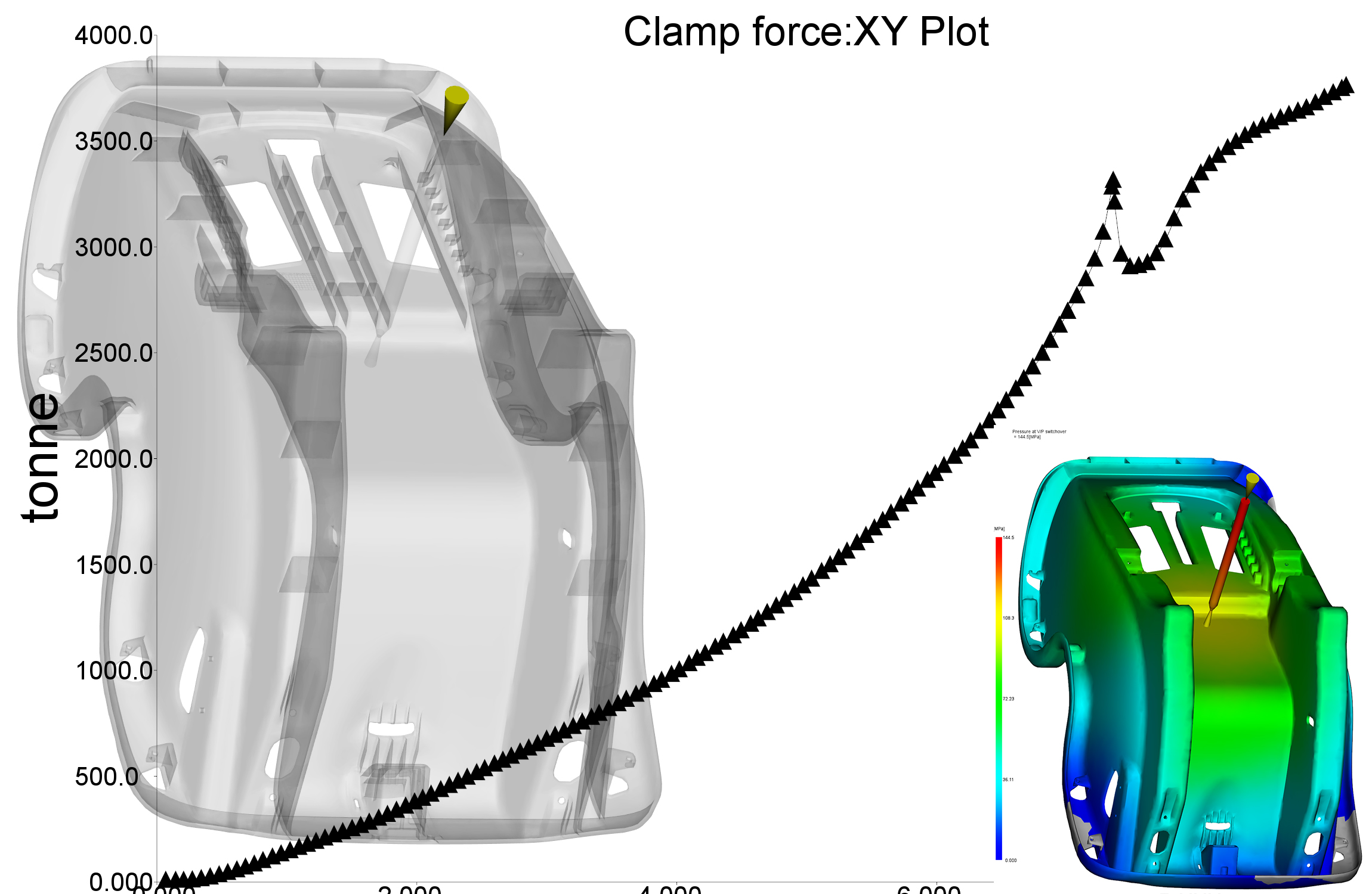
The pressure result at velocity-to-pressure switchover was approximately 145 MPa. Predicted clamp demand remained below the customer’s 4,000-tonne reference. These are separate simulation checks: injection pressure is not a measure of clamping force, and neither value is a measured production setting.
A core insert designed around deep-rib cooling
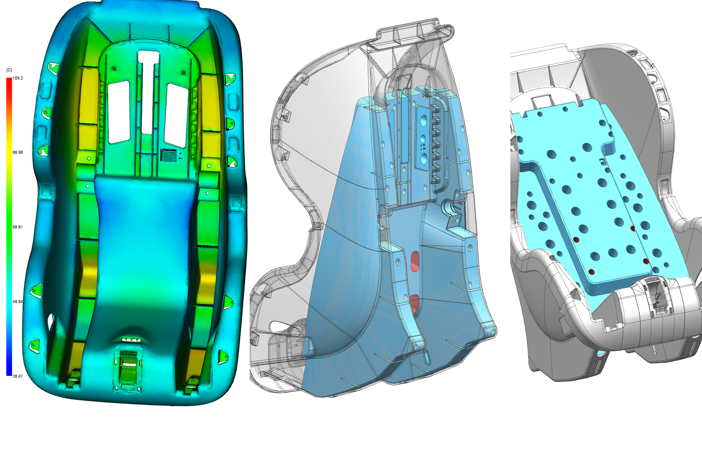
Two deep rib regions created an uneven cooling challenge. The core design incorporated a large separate insert so cooling passages could be arranged more effectively around these areas. The insert also improved machining access and allowed the insert and main core body to be processed in parallel.
This decision connected thermal requirements with manufacturability. The cooling layout and insert split were considered together during mold design and engineering, rather than leaving the water circuit until the steel geometry was fixed.
Six hydraulic cylinders, with a defined release sequence
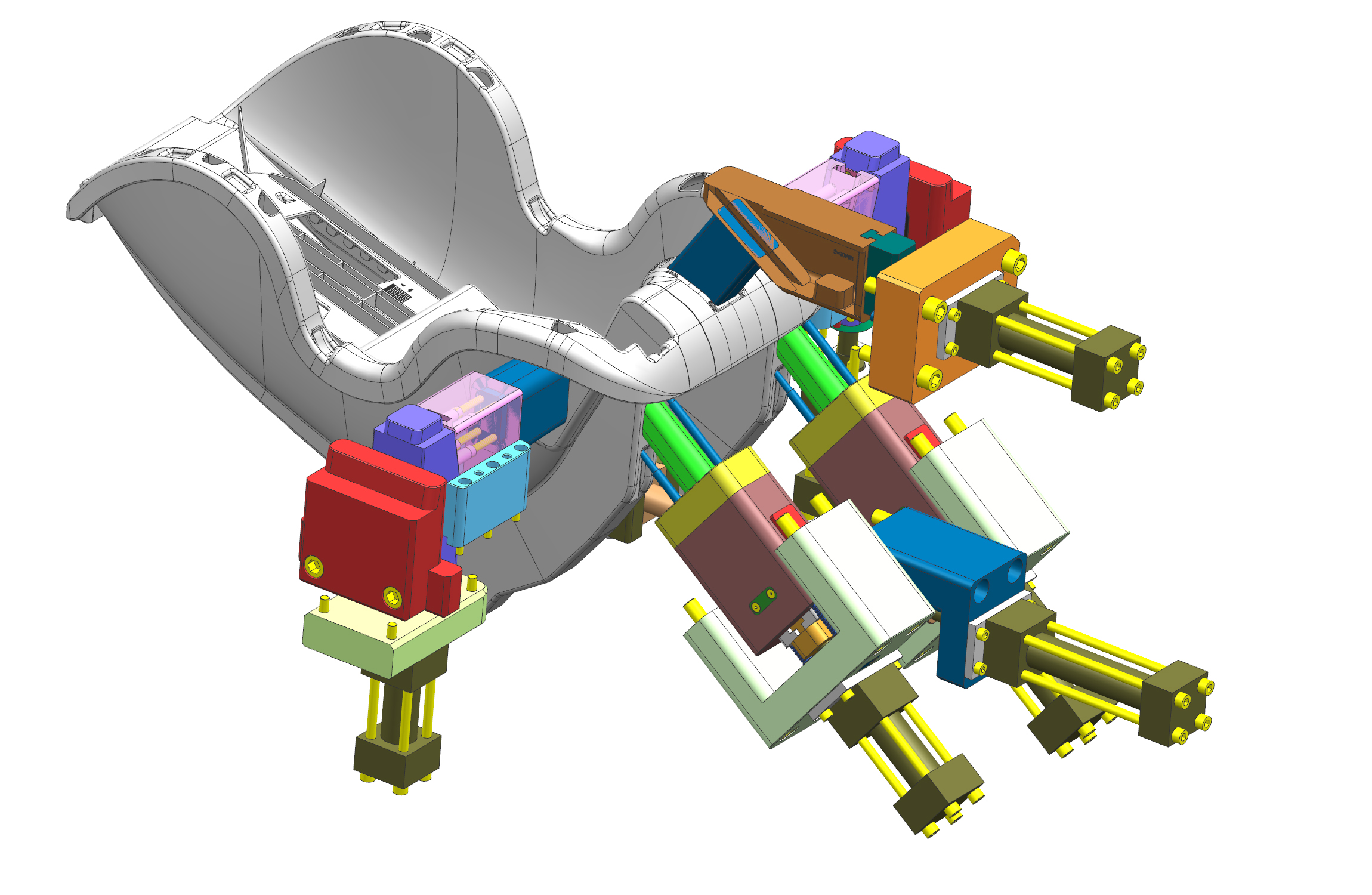
Side openings and base fixing holes run at angles to the main mold-opening direction. They therefore required side actions instead of a straight cavity-and-core release. Six hydraulic cylinders operate the core-pulling slides, with the sequence determined by which half of the tool carries each feature.
| Cavity-side hydraulic cores | Retract before mold opening; return after the mold has closed. |
|---|---|
| Core-side slides | Retract and return while the mold is open. |
Separating these movements addresses the interference risk created by the angled features. The tooling layout shows how the individual release directions fit around the shell and its base.
From machining to shipment preparation
Workshop photographs document cavity machining and the completed tool prepared for shipment. The dispatch record shows tooling packed in wooden crates. This custom injection mold manufacturing project brought the gate study, cooling insert and hydraulic release sequence into one physical tool.
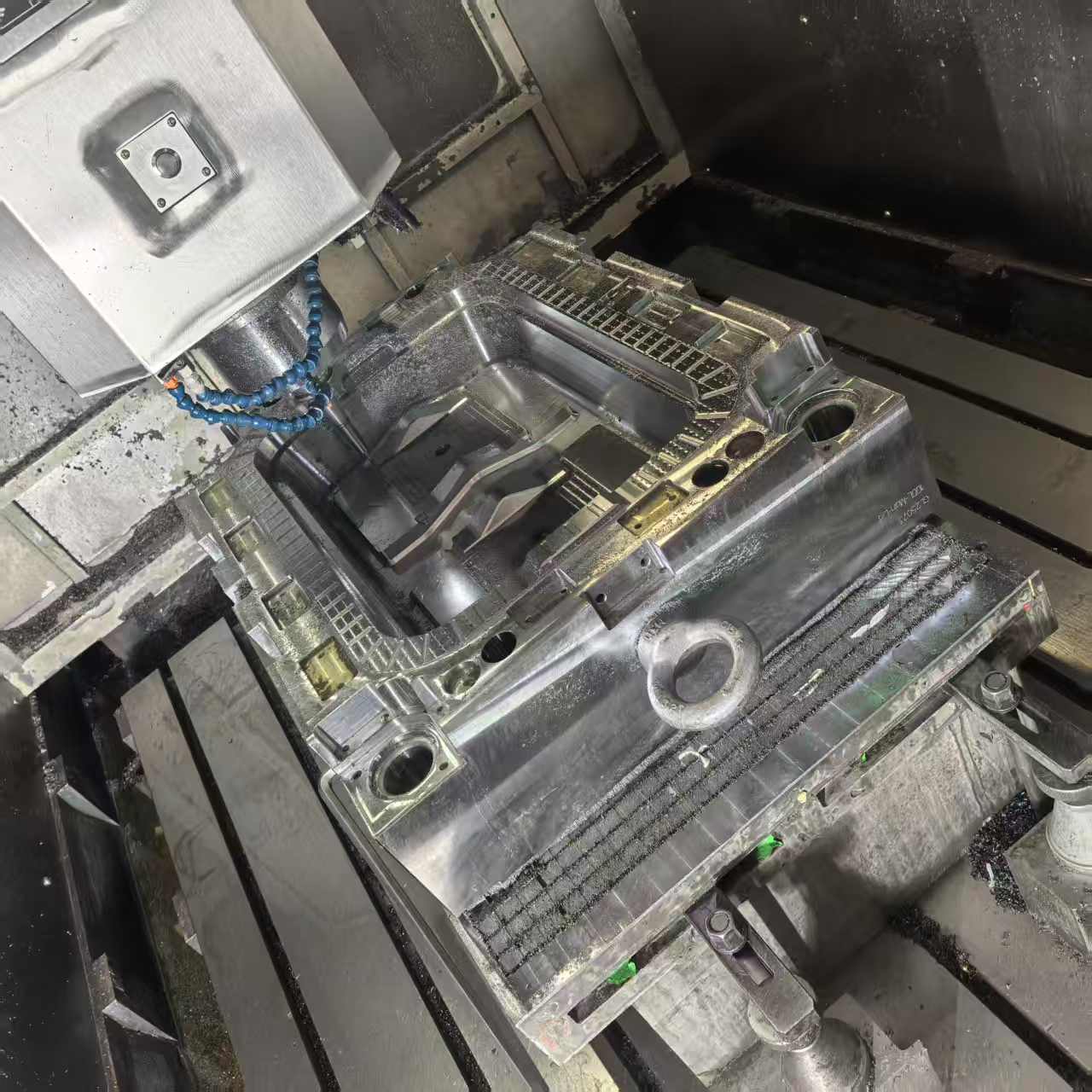
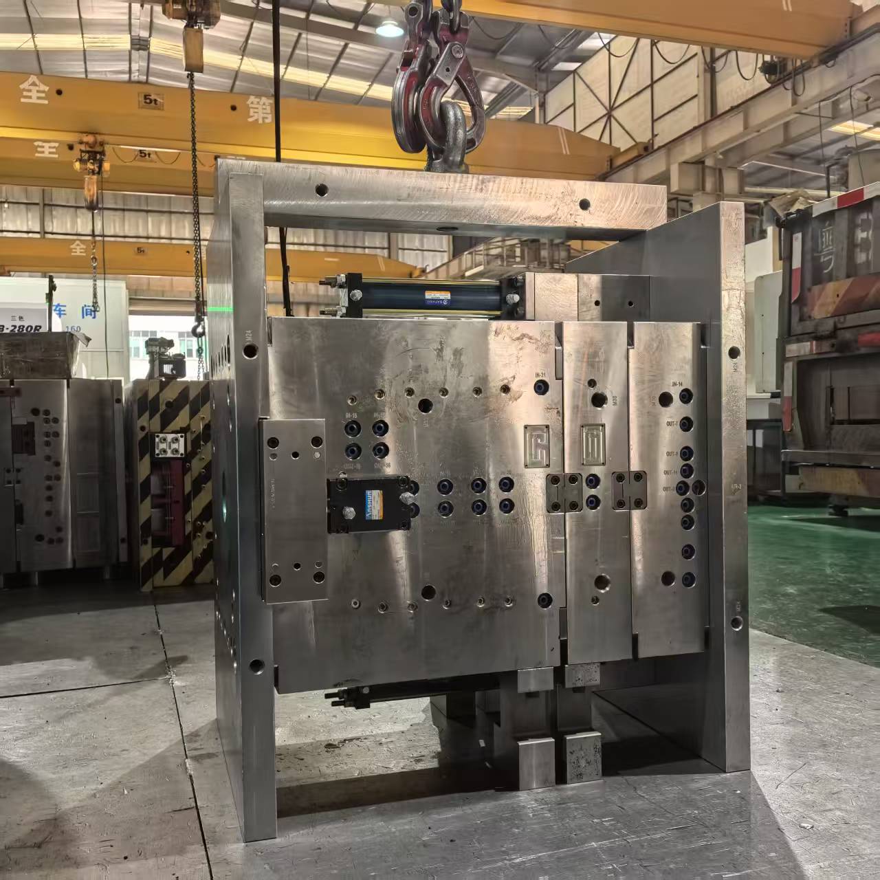
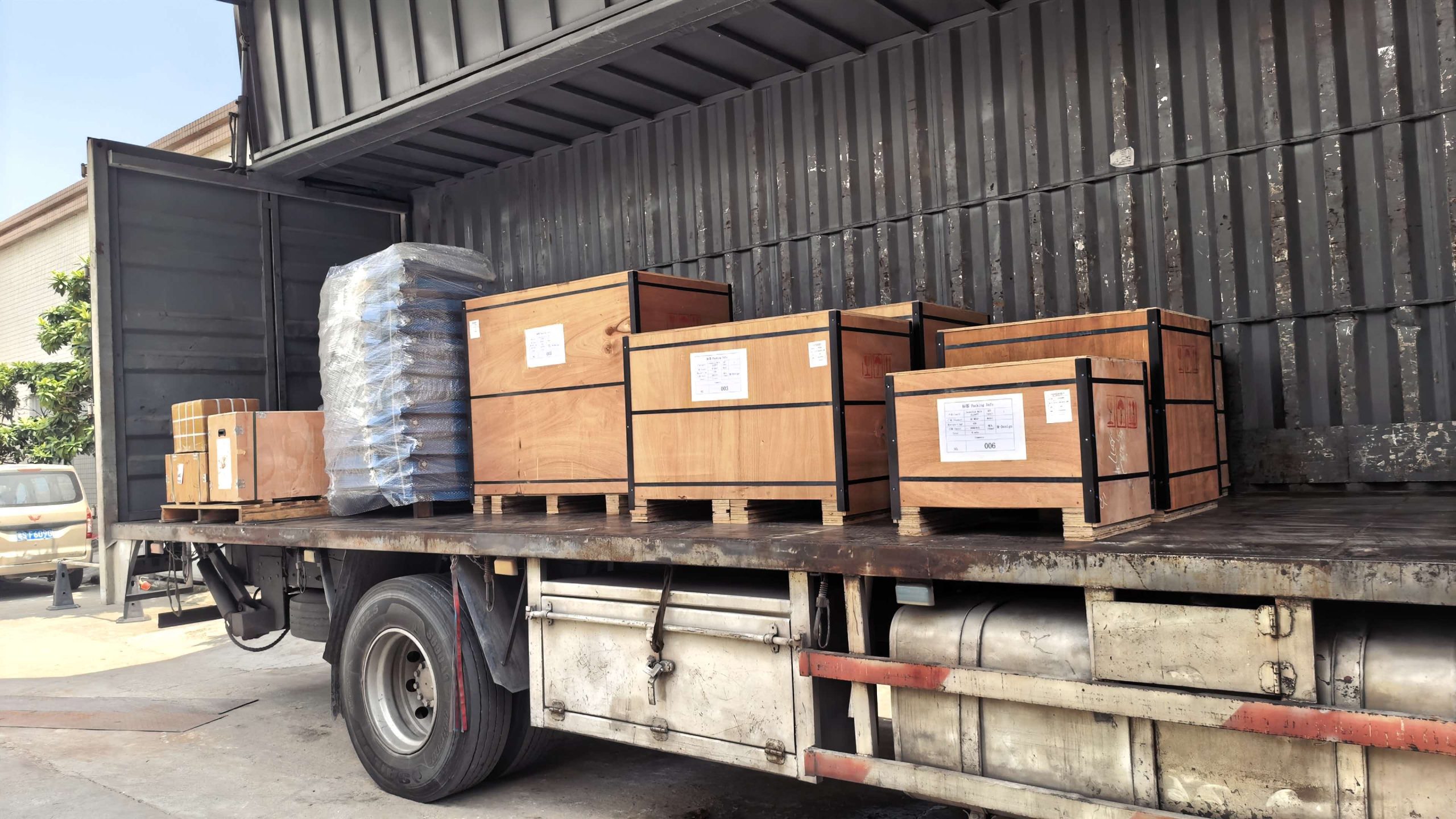
The case covers mold engineering, manufacture and dispatch preparation. Finished-seat safety approval is a separate product validation scope.
Discuss a similar tooling project
For a child car seat mold or another deep plastic shell with ribs and side openings, send your 3D part data, resin grade, production requirements and intended molding-machine specifications. We can review the gate strategy, cooling access and core-pulling sequence together.