
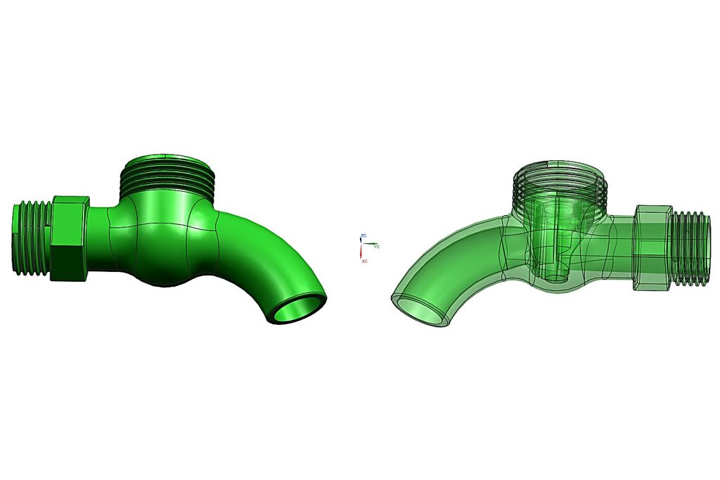
A plastic faucet body looks like a simple part. A body, a curved spout, two threaded ports. In tooling terms it is one of the more hostile shapes you can be handed.
Three separate undercuts fight the mold at the same time. The spout sweeps downward on an arc, so its internal waterway cannot be released by any straight-line core pull — pull it straight and the core collides with the curve it just formed. The inlet and outlet ports carry external threads that do not sit on the machine axis. The top boss overhangs the parting line vertically. Force any one of them out in a straight line and you drag hardened tool steel across a finished surface: a score line inside the waterway, or a torn thread flank on a port that has to seal.
This is a teardown of how we solved it — a 1×2 mold running three driven slides per cavity, a banana slider on a kinematic hinge to follow the curved waterway, and a strict closing and opening sequence that keeps six forming cores from colliding inside the same pocket of steel.

Project at a glance
| Part | Plastic faucet body — threaded inlet and outlet ports, down-swept curved spout |
| Cavitation | 1×2, mirrored layout, single parting line |
| Slides per cavity | 3 driven slides (1A/1B, 2A/2B, 3A/3B) |
| Forming cores per cavity | 6 forming cores on 3 independent drive directions |
| Undercuts released | Vertical top boss · horizontal threaded ports · curved spout waterway |
| Signature mechanism | Banana slider on a kinematic hinge, positioned by a limited boss |
| Motion control | Strictly sequential, mechanically interlocked — not press-timed |
| Serviceable wear items | Guide rails and wear plates, locking wedges, hinge pins, limited bosses |
| Resin / material | PA66 (Polyamide 66) |
| Clamping force | 120 Ton |
| Cycle time | 28 s / shot |
| Annual output | 70,000 pcs |
| Engagement | Custom-made plastic faucet mold (built to order) |
Built for PA66 on a 120 Ton press, this tool runs a 28-second cycle and is specified for an annual output of 70,000 faucet bodies. The numbers below are the production targets the tool was designed against, not a rating we rounded to look tidy.
1. Mold layout and overall architecture
Start with the layout, because on this part the layout is not a business decision — it is a mechanical constraint that happens to have a business answer.
What determines the size of this mold base is not the faucet. It is the slides. Each cavity needs three drive directions, and every direction needs its own pocket, guide rail, wear plates, travel clearance and locking wedge. Those mechanisms surround the cavity on three sides. Figure 2 shows the result: the two light-blue cavity blocks in the middle are almost lost inside the pink base, boxed in by Slider 1A/1B pockets at the top, the pink Slider 2A/2B pads left and right, and the magenta Slider 3A/3B assemblies running on the yellow guide rails at the bottom, with the gray wedge blocks locking the side cores against injection pressure.

A single cavity would have been simpler and safer, and for a low-run project that is the correct answer. We went to two cavities because the tooling cost per part is dominated by the slide assemblies, and those are reusable across cavities — the second cavity adds a cavity block and a set of wear items, not a second engineering program.
We stopped at two deliberately. Every additional cavity lengthens the runner, which raises fill pressure, which raises clamp tonnage, which forces a bigger press and a heavier base — the cost curve bends upward hard beyond two cavities. And there is a reliability argument: with six slides per shot, a single sticking slide stops the whole shot. A 1×2 keeps the mechanical risk in a range we can maintain, while still doubling output against a single cavity.
The mirrored symmetry is not cosmetic either. It balances fill between the two cavities and equalises cooling. On this part that matters because the inlet and outlet threads must assemble to standard fittings — if the two cavities cool at different rates, the thread dimensions drift apart between cavities and one of them ends up out of tolerance against the same gauge.
2. The three-slider undercut release system
A standard faucet has severe internal undercuts, and there is no straight-pull ejection path through any of them. What makes the tooling interesting is that the three undercuts do not share a release direction, so no single slide can serve two of them. One slide travels one way. Figure 3 is the labelled front view, and it is the clearest way to see the division of labour.

Slider 1A/1B travel vertically to release the top boss. Slider 2A/2B travel horizontally to pull the threaded cores out of the inlet and outlet ports. Slider 3A/3B travel from the bottom and drive the linkage that positions the banana slider — the subject of the next section.
The sequence problem is visible right here in the drawing. If Slider 2A/2B retract before Slider 1A/1B have cleared the top boss, the threaded core drags sideways across the thread flank it formed. On a plastic thread that shows up as galling and stress whitening, and a whitened thread is a thread that will crack at assembly torque. Run it the other way and the boss shears instead. Neither failure is subtle, and neither is repairable in the part — which is why the sequence is enforced mechanically rather than trusted to the press.
It is also worth being straight about the maintenance side of this. Six slides mean six sets of guide surfaces, six locking wedges and six travel limits to keep clean and adjusted. Guide and wear surfaces are specified as hardened and nitrided precisely because they see millions of cycles of sliding contact. A mold with this much mechanism needs a maintenance schedule, and any quote for this type of tooling should include one. If your project does not need the slides, the honest engineering answer is to delete them — our comparison of lifters and sliders covers when each mechanism actually earns its cost.
3. The core innovation: banana slider and kinematic hinge
The blue component in Figure 4 is the reason this mold exists in this form. Behind the spout, the waterway curls downward. The undercut is not merely at an angle to the mold axis — it sits behind the curve, which means that from the outside there is no straight line along which the core can be extracted without cutting through material it already formed.

We evaluated the four standard answers before settling on this one.
A collapsible core was rejected because it leaves witness lines on the inside of the waterway. On a faucet, that inside surface is a water passage and often a sealing seat — seams there are a leak risk, and collapsible cores have a limited service life on top of that.
A low-melt or dissolvable core was rejected on cycle time and repeatability. You are effectively adding a second process step and a waste stream to every part, and the bore geometry drifts with the melt-out.
An air-assist mandrel works well for long, roughly straight bores, but this waterway is a compound curve that terminates in a threaded port. The mandrel cannot follow the arc, and the threaded end blocks a clean axial pull.
So we used an arcuate core pull: the banana slider. The core travels along the arc it needs to travel along, entering and leaving on the same path, so the forming surface never scrapes the plastic.
The mechanism that makes this work is a kinematic hinge. The linear stroke of Slider 3A/3B pushes a hinged link, and the hinge converts that translation into a smooth curved sweep of the core. The core enters along the arc and leaves along the arc.
The detail that decides whether this survives production is the limited boss. Look at the round pin sitting in the circular pocket on the banana slider. It is tempting to think of the hinge pin as the load-bearing element — it is not. The hinge pin guides. The limited boss is the hardened stop that defines the end-of-stroke position and takes the cavity pressure, so the injection load never reaches the hinge pin as a bending moment.
Leave the limited boss out, or undersize it, and the hinge pin carries the whole forming load on a small cross-section. It fatigues, the core creeps slightly out of position, and the failure shows up as flash on the inside of the waterway — the hardest place on the part to detect and the most expensive place to have a defect. This is the single most important design decision in the mold, and it is a two-millimetre-looking feature.
4. Comprehensive slider arrangement and mechanism
Figure 5 strips the mold down to mechanism only, which is the view to study if you want to understand the choreography. All six slides are shown with their banana sliders, hinges, guide rails and the linkage that connects Slider 3 to the banana slider.

Read the drawing as three converging directions. Slider 1A/1B come down from the top and carry the cores for the vertical top undercut. Slider 2A/2B come in from left and right and carry the threaded cores. Slider 3A/3B push up from the bottom and tilt the banana sliders into position through the hinge. The banana slider sits at the intersection of all three — which is exactly why the timing rules in the next two sections exist.
Two engineering points hide in the details of this view.
First, the guide surfaces are bolted, replaceable wear plates. You can see the yellow strips with their screw pattern running along the travel direction on both sides of the lower slides. The rail is the part that wears, so the rail is the part you replace. Rebuilding a worn guide directly into the slide body means scrapping a slide block; bolting a strip on means replacing a strip during a maintenance window.
Second, the travel envelopes overlap. Near the spout root, the swept volume of the banana slider and the forming envelope of Slider 1 share the same space at different points in the cycle. That interference cannot be checked in the closed position alone — it has to be verified in 3D across the full stroke, at both extremes and through the transition. Interference checking of the complete motion envelope, not just the assembled state, is what keeps a design like this out of trouble. It is also the step that most often gets skipped when a slide-heavy mold is quoted on price alone; our DFM checklist lists the interference and clearance checks we run before steel is cut.
5. Sequential control: the mold closing phase
In tooling this complex, timing is not a refinement — it is the difference between a mold that runs for years and a mold with a cracked insert. Figure 6 shows the closing sequence with the engagement arrows marked.

Slider 3 engages first. That is not a convenience — it is a precondition. Slider 3 establishes the hinge’s pivot position, and until that pivot is fixed the banana slider has no defined axis to rotate about. Move the banana slider before its pivot is established and the core tip arrives unsupported, the hinge linkage is loaded in the wrong direction, and on the next shot the melt pressure pushes the tip off position. The result is a mis-formed waterway that looks acceptable on a visual check and leaks in service.
With the foundation set, the banana slider swings into its final forming position, limited by the boss. Only then do Slider 1A/1B and Slider 2A/2B complete their travel and lock, so the cavity is fully closed and supported before the mold faces clamp.
Run all of it simultaneously and the banana slider tip is moving into space that Slider 1’s core has not yet vacated. In hardened steel against hardened steel, that means a chipped edge at best; where a slide insert carries a thin forming feature, it can crack the insert outright. A cracked insert on this mold means re-cutting the core geometry that forms the waterway — the most expensive repair in the tool.
The important implementation detail is that the sequence is enforced by mechanical hard stops and interlocks, not by programming the press. Press timing drifts with temperature, hydraulic response and age. A hard stop does not. On a mechanism with this many overlapping travel envelopes, the sequence belongs in the steel.
6. Sequential control: the mold opening phase
The opening sequence runs the same logic in reverse, and Figure 7 shows it with the banana slider released.

Slider 3 retracts first. That retraction is what creates the clearance the banana linkage needs; only once the clearance exists is the banana slider released to pull away along its arc. Then the remaining slides withdraw — Slider 2A/2B back out of the threaded ports and Slider 1A/1B clear the top boss — and with every undercut released the part is free to be pushed off.
Reverse the order and the failure is mechanical and cumulative. Release the banana slider first, while Slider 3 is still engaged, and the core tip sweeps against the still-seated shoulder instead of swinging clear. You get scoring on the core, and — more damaging — a core whose forming geometry has shifted slightly. On the next shot the waterway is marginally out of position. Slight deviations like this do not announce themselves; they accumulate as a slow drift in part quality across a production run, and the resulting wall-thickness variation is nearly impossible to trace back to a slide that was released half a second early.
There is a functional reason this matters more here than on a cosmetic part. The internal waterway and the port seats on a faucet are sealing surfaces. A scuff inside the waterway is not a cosmetic defect you can argue about — it becomes a leak at the customer’s assembly line, or worse, a leak in a finished installation. The part’s appearance is the least of it; what we are protecting through the whole opening sequence is a sealing geometry that nobody will ever inspect on the factory floor.
The measurable outcome of getting this right is simple: no drag marks, no thread damage, no deformation on ejection, and a waterway surface that comes out of the tool exactly as the core formed it.
7. Why this advanced mold design excels
Integrating a kinematic hinge with a sequentially controlled banana slider puts this tool in territory a standard mold cannot reach. Straight-pull tooling cannot form these undercuts at all; simpler slide layouts can form them but drag on release. What this design buys is a release sequence that leaves every functional surface intact: clean threaded ports that assemble without rework, a curved waterway with no drag marks on its sealing surfaces, and zero defects on geometry that a two-plate mold physically cannot produce.
It also buys tool life, and not by accident. Load is deliberately routed into hardened stop features and replaceable wear items — the limited boss, the guide rails, the locking wedges — instead of into pivots and pins. Wear is concentrated in parts designed to be swapped. Friction and scoring, the two things that kill a slide-heavy mold early, are engineered out of the load path rather than managed with grease. And the 1×2 balanced layout delivers that at twice single-cavity output. For a broader look at the design decisions that separate a mold that stays stable from one that fights you, see how to make a stable injection mold; for a second worked example with a different undercut problem, our 2K electronic enclosure project breaks down a two-shot tool in the same way.
But the part of this design we would defend hardest is knowing when not to build it. This is not a mold to specify out of ambition:
| If your part conditions are… | We would not build this mold |
|---|---|
| The spout were straight instead of curved | A conventional angle-pin slider releases it. The banana mechanism and its hinge are cost with no return. |
| The waterway could tolerate internal seams | A collapsible core is cheaper to build. Worse part, adequate if the bore is not a sealing surface. |
| Annual volume were low | Change the part, not the mold — split the body into two bonded pieces or add a parting-line feature, then run simple tooling. |
| The threads could be machined or inserted after molding | Delete Slider 2A/2B and drop two forming cores per cavity. |
| The component had to be silicone (LSR) | Different process envelope; the sequencing logic transfers, the cold-runner steel approach does not. |
The engineering judgement is not “how many sliders can we fit”. It is identifying which single feature forces the complexity, and then refusing to add mechanism the part does not require. Here, that feature is the down-swept curved waterway, and the banana slider is the minimum mechanism that releases it.
Ready to bring a complex part design to life? Send us your 3D data and application requirements and our engineering team will run a full DFM analysis — undercut mapping, release direction study, interference checking and a manufacturable tooling proposal with a competitive quote. Contact our engineering team to start.
Frequently asked questions
What is a banana slider in injection molding?
A banana slider is a curved core-pulling mechanism that releases an undercut along an arcuate path instead of a straight line. It is used when a curved internal feature — such as a down-swept faucet spout waterway — cannot be released by any linear pull. The core travels in along an arc and leaves along the same arc, so the forming surface never scrapes the plastic. In this mold, the banana sliders (3A and 3B) are driven by a kinematic hinge that converts the linear stroke of Slider 3 into a curved trajectory.
Can a plastic faucet be molded in a standard two-plate mold?
Not in this geometry. A two-plate mold releases on a single straight line, and this faucet has three undercuts that do not share a release direction: a vertical top boss, two horizontal threaded ports sitting off the machine axis, and a curved waterway behind the spout. Straight-pull ejection would drag the core across a sealing surface or tear the thread flanks. It also cannot be solved by adding slides alone — the curved waterway needs an arcuate core path, which is why the banana slider and sequentially controlled drive linkage are required.
How many sliders does a 1×2 plastic faucet mold need?
Three driven slides per cavity, so six in total across the 1×2 layout: Slider 1A/1B for the vertical top undercut, Slider 2A/2B for the horizontal threaded ports, and Slider 3A/3B to drive the bottom linkage that carries the banana sliders. Each slide travels in one direction only, which is why the three undercut types require three separate mechanisms rather than one combined slide.
Why is sequential control needed during mold closing and opening?
Because the travel envelopes of the slides overlap. On closing, Slider 3 must engage first to establish the hinge pivot before the banana slider moves into position; otherwise the core tip arrives unsupported and melt pressure pushes it off position on the next shot. On opening, Slider 3 must release first to create clearance before the banana slider is released — reverse the order and the core tip sweeps against a still-seated shoulder, scoring the core and drifting the waterway geometry. Running the strokes simultaneously risks collision between hardened steel components. The sequence is enforced by mechanical hard stops and interlocks rather than by press timing, because press timing drifts and hard stops do not.
What is a limited boss, and why does it matter?
The limited boss is the hardened pin that sits in the circular pocket on the banana slider. It has two jobs: it defines the end-of-stroke position of the slider, and it absorbs the cavity pressure during injection. The hinge pin beside it only guides the motion. If the limited boss is omitted or undersized, the hinge pin carries the forming load on a small cross-section, fatigues over time, and allows the core to creep out of position — which shows up as flash on the inside of the waterway, the hardest place on the part to detect.
How do you maintain a mold with six forming cores?
By designing the wear into replaceable components. The guide rails use bolted wear plates rather than rails cut directly into the slide body, so a worn guide is swapped as a strip instead of scrapping a slide block. Guide and wear surfaces are specified as hardened and nitrided because they see sliding contact over millions of cycles. The serviceable items on this tool are the guide rails and wear plates, the locking wedges, the hinge pins and the limited bosses — checked on a schedule as part of normal preventive maintenance, not on failure.