
ENGINEERING DESIGN CASE STUDY
Shower Head Injection Mold Design with Arc Core Pulling
A two-cavity ABS housing concept using hydraulic rack-and-pinion actuation to release a curved internal passage.
This shower head injection mold design study covers part geometry, tool layout, filling analysis and a synchronized arc core pulling mechanism.
Project requirements
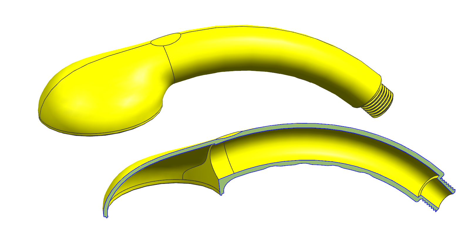
The part is a plastic handheld shower head housing with a threaded connection at the bottom. The specified molding material is ABS. Its visible surfaces require polishing, with subsequent electroplating intended for the finished part.
| Design item | Proposed specification |
|---|---|
| Application | Handheld shower head housing |
| Material | ABS |
| Layout | Two cavities |
| Mold and runner | Three-plate mold with a cold runner |
| Internal feature | Circular-arc passage; nominal arc diameter 270 mm |
| Release approach | Hydraulic rack-and-pinion arc core pulling, with separate sliders for the external thread |
| Project stage | Engineering design and simulation study |
Why the curved passage needs arc core pulling
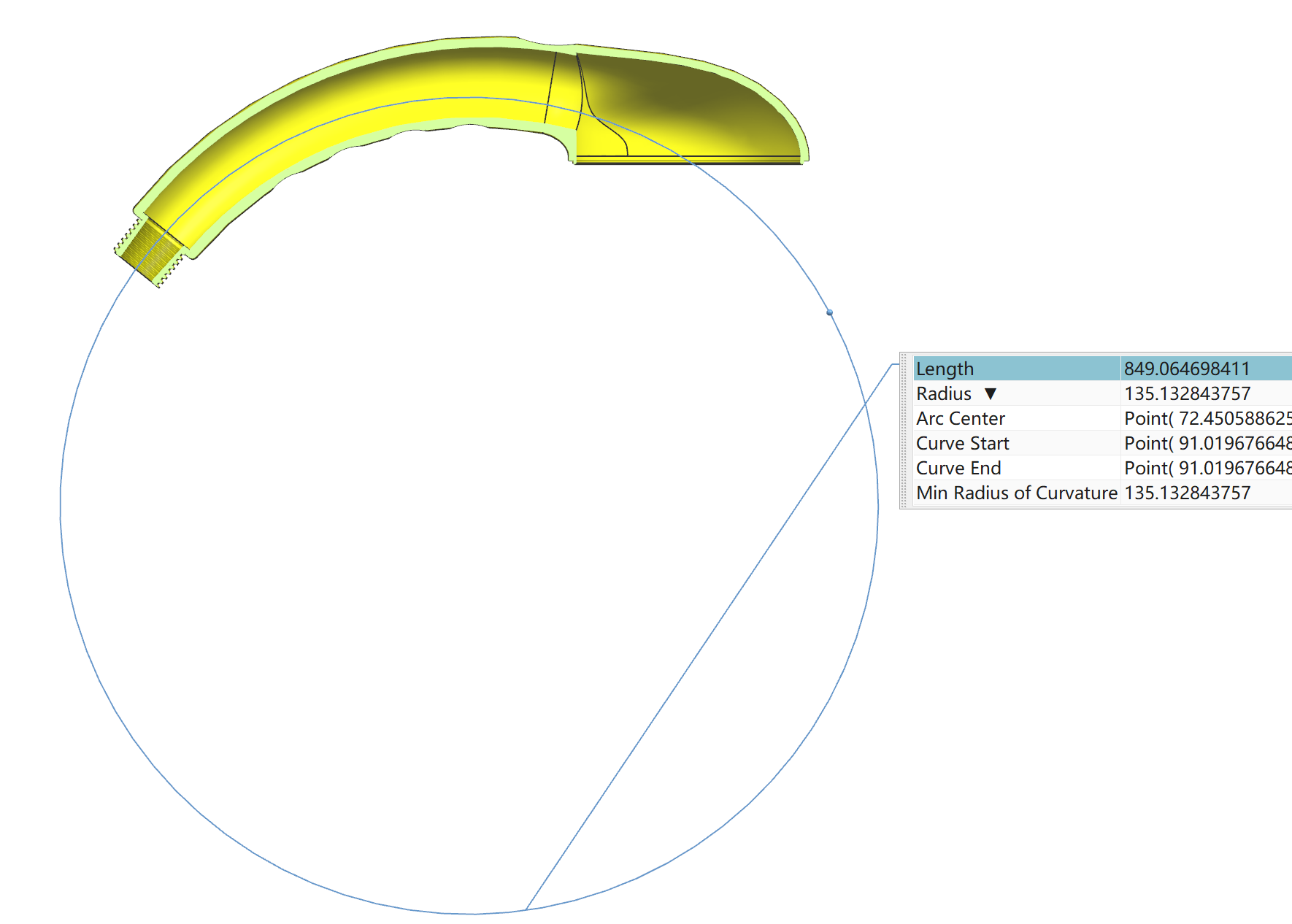
The internal passage follows a regular circular arc. The design therefore uses a curved core that withdraws along that arc, rather than pulling straight through the curved bore. The geometry review sets the rotation center and the path of the core.
The calculation uses a nominal internal arc diameter of 270 mm. This dimension describes the arc followed by the passage, not the diameter of the water channel. The CAD measurement shown below is approximately 135.13 mm in radius.
This geometry review is part of our mold design and engineering work for custom injection molds.
Two-cavity mold layout and material selection
The proposed tool is a two-cavity, three-plate injection mold with cold runner feeding. The design record specifies S136 for the cavity and core inserts, H13 for the sliders, S7 for the wear blocks and custom NAK80 racks.
The threaded end is released using a dovetail-guided slider arrangement. This is a separate release feature from the curved core mechanism inside the handle.
Filling analysis
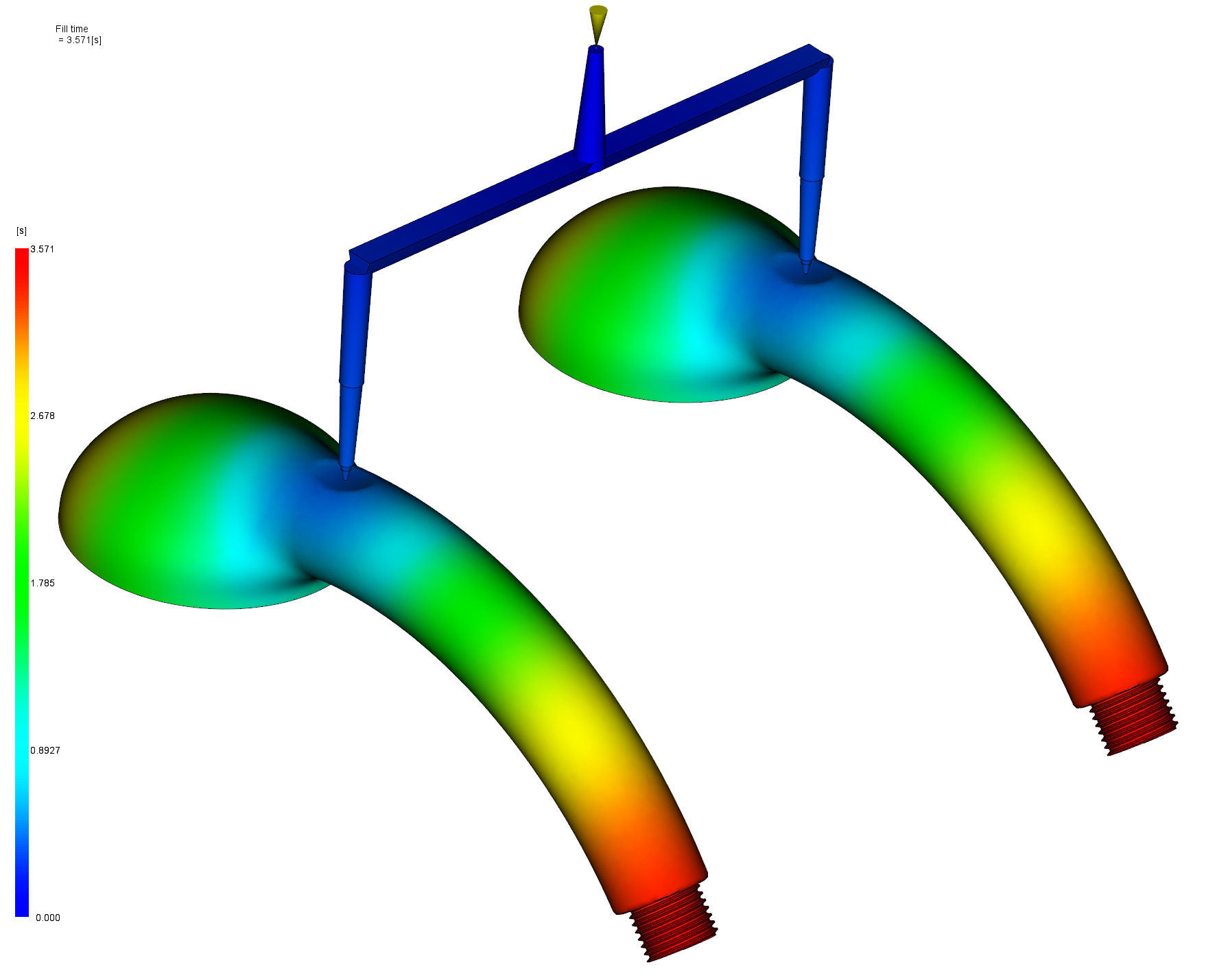
The supplied filling simulation supports the feasibility of the proposed runner layout at the design-study stage. Its color map shows filling through both cavities, with a displayed fill time of 3.571 seconds. That value is a simulation output; it does not establish production cycle time, dimensional acceptance or surface finish.
How the rack-and-pinion mechanism works
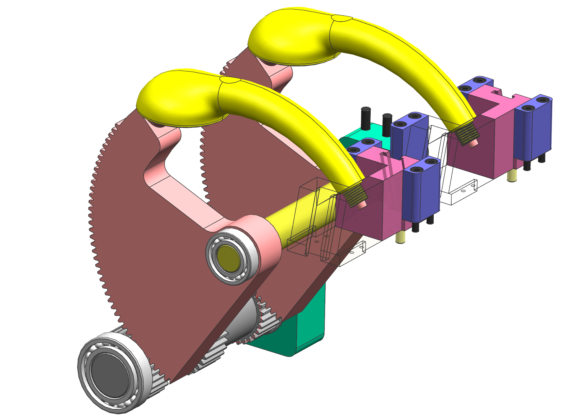
A hydraulic cylinder provides linear motion to a rack. The rack turns a pinion on a common shaft, which drives the two gear-sector core carriers in synchronization. Rotation of the carriers withdraws the curved cores along the internal arc of each housing.
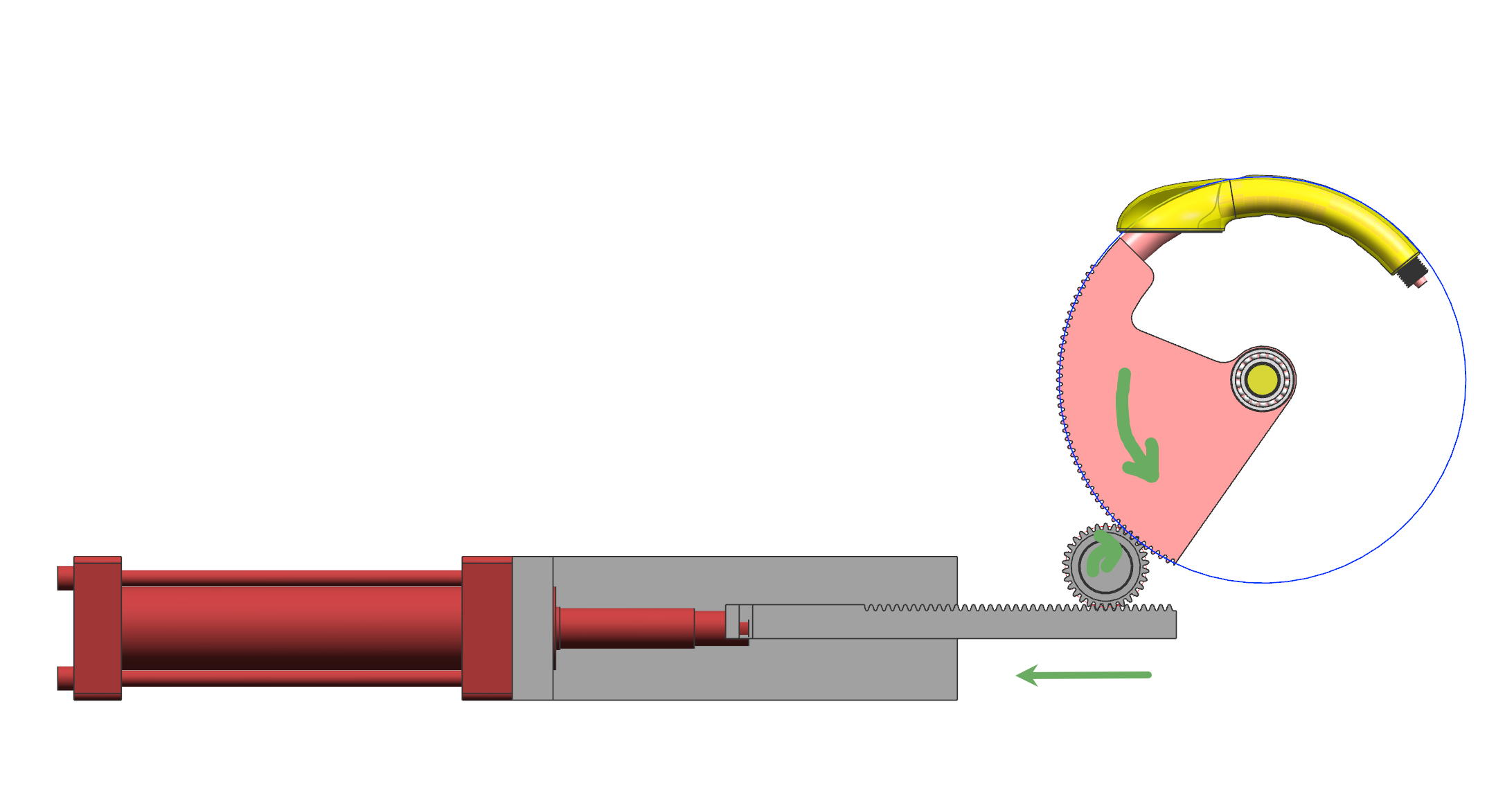
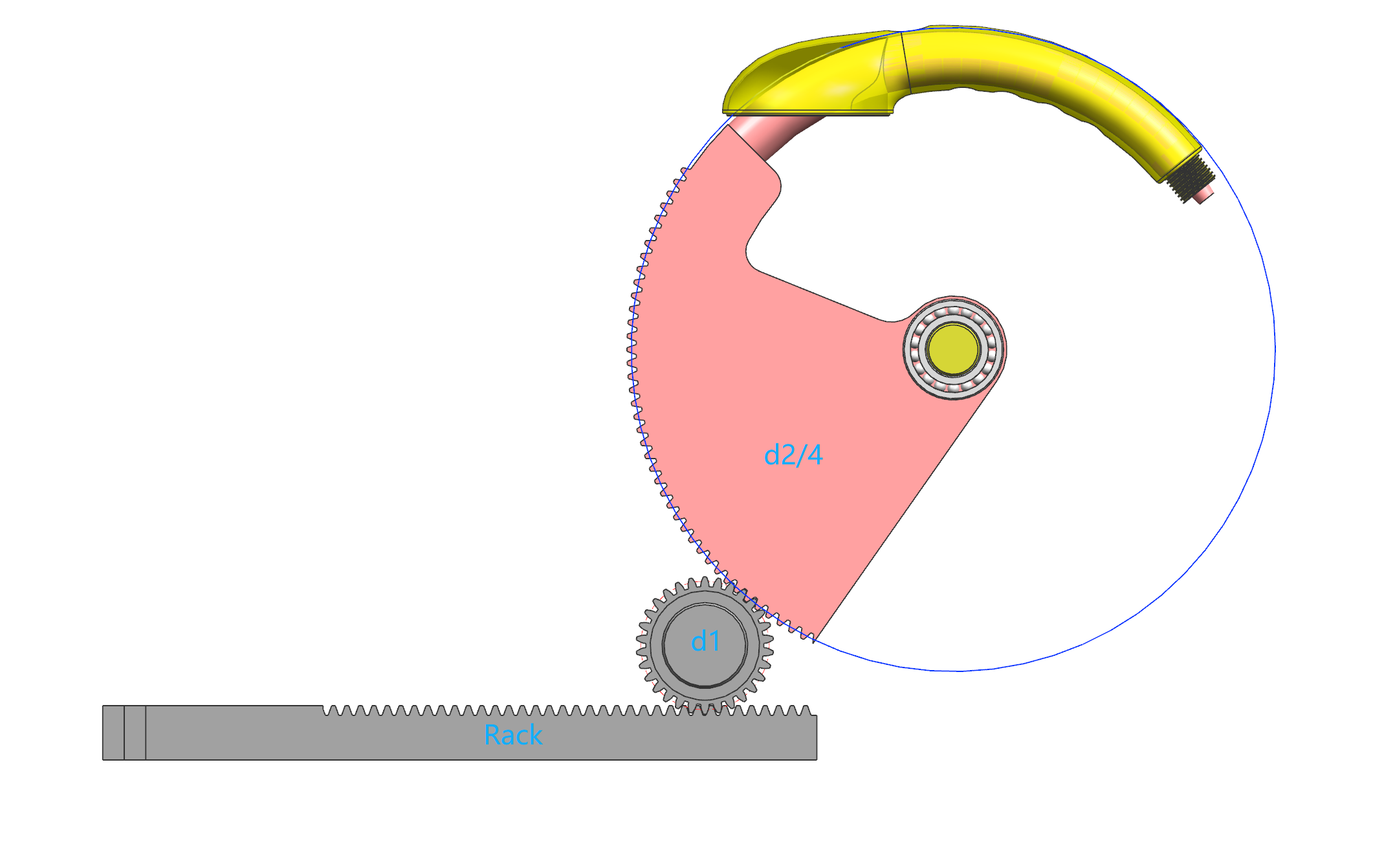
The driven component is designed as a cam-like sector with gear teeth because only approximately one quarter of the equivalent full gear is needed for the working range. Using a sector is intended to reduce the space occupied by the mechanism. The pitch circles of the pinion and driven sector must be tangent at their designed center distance.
Gear geometry and calculation example
The design uses module m = 2 mm, pinion pitch diameter d₁ = 60 mm and driven pitch diameter d₂ = 300 mm. The following values describe the nominal gear geometry. The 150-tooth value is the equivalent full-gear tooth count, not the number of teeth physically present on the sector.
| Parameter | Relationship | Calculated value |
|---|---|---|
| Pinion tooth count | z₁ = d₁ / m | 30 |
| Equivalent driven tooth count | z₂ = d₂ / m | 150 |
| Gear ratio | i = d₂ / d₁ = z₂ / z₁ | 5:1 |
| Center distance | a = (d₁ + d₂) / 2 | 180 mm |
| Rack circular pitch | p = πm | 6.283 mm |
| Rack travel per pinion revolution | L = πd₁ | 188.50 mm |
For an illustrative pinion speed of 100 rpm, the driven sector would rotate at 20 rpm. With a 10 N·m pinion input torque and an assumed gear-pair efficiency of 0.95–0.98, the corresponding output torque is approximately 47.5–49 N·m for a single loaded gear pair.
Using F = 2T / d with d₁ = 0.06 m gives an ideal tangential rack force of 333.3 N for that 10 N·m torque. This is a gear calculation example, not the required cylinder force for the complete two-core system. Actual sizing must account for both core loads, load sharing, friction, locking and operating conditions.
The geometry relationships follow standard spur gear and rack calculations. Reference: KHK gear dimension calculations.
CAD motion sequence
The motion study illustrates the intended core positions before and after withdrawal. In the molding position, the curved cores are seated and locked. After the mold opens, the hydraulic cylinder moves the rack and the synchronized gear train rotates both cores out of the housings.
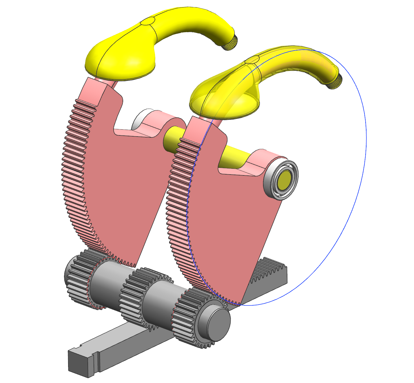
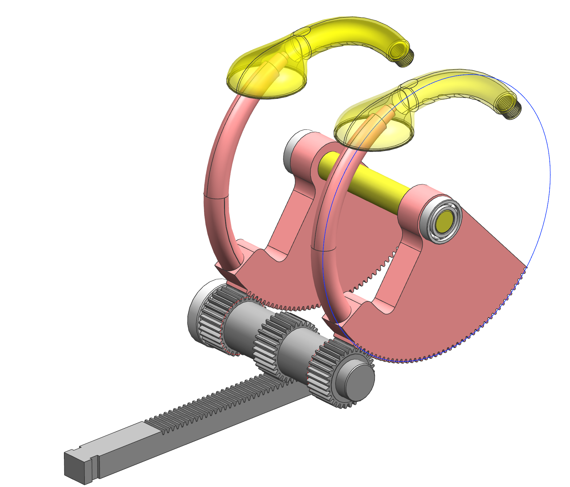
The sequence still requires detailed checks of the locking arrangement, travel limits, interference clearances and the timing of the thread-forming sliders before a production tool can be validated.
Design review outcome and next checks
This engineering case study establishes a proposed mold layout and an arc core pulling concept for the ABS shower head housing. The supplied CAD and filling analysis document the design approach; this case does not report a physical mold trial, customer acceptance or delivery.
Further engineering work includes tooth-contact and tooth-root strength checks, shaft and bearing loads, rack mounting tolerances, lubrication and cylinder sizing. The polished molding surfaces and intended electroplating finish also need to be assessed against molded samples.
Discuss a similar injection mold project
If you are choosing a plastic injection mold maker for a housing with a curved passage or threaded features, share the part drawings, resin requirements, finish and expected production quantity. DFMOLD HK can review the tooling approach and the checks needed before mold manufacturing.